
Influence of Abutment Design on Biomechanical Behavior to Support a Screw-Retained 3-Unit Fixed Partial Denture
Guilherme da Rocha Scalzer Lopes 1
, Jefferson David Melo de Matos 1,2 , Daher Antonio Queiroz 3,* ,
João Paulo Mendes Tribst 4
, Nathália de Carvalho Ramos 1,5 , Mateus Garcia Rocha 2
, Adriano
Baldotto Barbosa 6
, Marco Antonio Bottino 1
, Alexandre Luiz Souto Borges 1 and Renato Sussumu Nishioka 1
1 Department of Biomaterials, Dental Materials and Prosthodontics, Institute of Science and Technology, São Paulo State University (Unesp), São José dos Campos 12245-000, Brazil
2 Center for Dental Biomaterials, Department of Restorative Dental Sciences, University of Florida (UF Health), Gainesville, FL 32611, USA
3 Department of Restorative Dentistry & Prosthodontics, The University of Texas Health Science Center at Houston (UTHealth) School of Dentistry, Houston, TX 77054, USA
4 Department of Oral Regenerative Medicine, Academic Centre for Dentistry Amsterdam (ACTA), The University of Amsterdam and Vrije Universiteit, 1081 LA Amsterdam, The Netherlands
5 Department of Dentistry, Universidade São Francisco (USF), Bragança Paulista 12916-900, Brazil
6 Midwest Dental Arts Inc., Palm Bay, FL 32909, USA * Correspondence: [email protected]
Abstract: This study aimed to evaluate the biomechanical behavior of Morse taper implants using different abutments (CMN abutment [(CMN Group] and miniconical abutments [MC Group]), indicated to support a screw-retained 3-unit fixed partial denture. For the in vitro test, polyurethane blocks were fabricated for both groups (n = 10) and received three implants in the “offset” configuration and their respective abutments (CMN or MC) with a 3-unit fixed partial denture. Four strain gauges were bonded to the surface of each block. For the finite element analysis, 3D models of both groups were created and exported to the analysis software to perform static structural analysis. All structures were considered homogeneous, isotropic, and elastic. The contacts were considered non-linear with a friction coefficient of 0.3 between metallic structures and considered bonded between the implant and substrate. An axial load of 300 N was applied in three points (A, B, and C) for both methods. The microstrain and the maximum principal stress were considered as analysis criteria. The obtained data were submitted to the Mann–Whitney, Kruskal–Wallis, and Dunn’s multiple comparison test (α = 5%). The results obtained by strain gauge showed no statistical difference (p = 0.879) between the CMN (645.3 ± 309.2 µε) and MC (639.3 ± 278.8 µε) and allowed the validation of computational models with a difference of 6.3% and 6.4% for the microstrains in the CMN and MC groups, respectively. Similarly, the results presented by the computational models showed no statistical difference (p = 0.932) for the CMN (605.1 ± 358.6 µε) and MC (598.7 ± 357.9 µε) groups. The study concluded that under favorable conditions the use of CMN or MP abutments to support a fixed partial denture can be indicated.
1. Introduction Osseointegrated implants are used safely in the rehabilitation of partially edentulous patients; however, this treatment can present long-term complications [1]. The two main implant failures are peri-implantitis and occlusal overload. These complications can act in association or independently, and both cause marginal bone loss which can lead to implant loss in advanced cases [2,3]. In the rehabilitation of partially edentulous patients, implant placement can be affected by several factors, including bone height or the anatomy of the region [4]. The implant configuration determines the load incidence pattern in that region which consequently affect the biomechanical behavior through the stress distribution between ductile materials and microstrains at the peri-implant bone [5,6]. When an implant is under functional load, the bone tissues receive a mechanical stimulus and undergo strain. This deformation is expressed with the letter ε and is defined as the relative change in bone length, often being expressed in microstrain (µε) [7]. A bone strain of 1000 means a 0.1% deformation [7], therefore bone strain in the 50–150 range allows the bone remodeling process to be kept stable, while 1500 µε tends to promote lamellar remodeling to overcome the mechanical requirement. On the other hand, 3000 µε is the physiological bone limit and when the load exceeds this limit, the implant may fail in this overloading scenario due to tissue damage [8]. To prevent peri-implant bone loss, it is important to know the masticatory system and the biomechanical behavior of all components of the implant rehabilitation, since the bone tissues are influenced by the occlusal loads transmitted to the implant [9]. Different implant systems provide many components/abutments, which can improve the prosthetic solution but also can hinder its correct selection. The correct abutment selection positively influences long-term treatment success, so it is essential to expand the knowledge on the subject and discuss new prosthetic possibilities [10]. In this context, the CMN abutment has a geometry with a height of 3.5 mm and an anti-rotational configuration, that is, it is indicated to support single prostheses screwed on the implant. However, the use of rotational copings on these abutments allows the manufacture of fixed partial dentures and, if their biomechanical behavior is compatible with this purpose, its indication can be extended to different configurations of prostheses on implants. Clinical studies observed during investigations of the biomechanical behavior of implants the magnitude of the loads applied at the prosthesis/abutment level and claimed that these same stresses cannot be found at the implant-bone interface. This limitation is due to many practical and ethical obstacles to realizing a controlled clinical trial able to evaluate occlusal overloading [11]. To improve the understanding of implant rehabilitation behavior, more studies using bioengineering can be used, such as finite element analysis (FEA) and strain gauges analysis (SG) [12,13]. The numerical method using FEA allows the simulation of the load application and provides information regarding their respective stress and strain distributions [6], while the electric linear SG is a tool with high sensitivity that allows the analysis of strain peaks [14]. The association of these two methodologies allows a correct analysis of the events evaluated and aid to understand some clinical manifestations [15]. Given the foregoing, the present study aimed to evaluate the biomechanical behavior of Morse taper implants using CMN abutment (experimental group) and miniconical abutment (control group) to support a screw-retained 3-unit fixed partial denture, under axial load, using FEA and SGs. The null hypotheses were that the stress and strain distribution would be higher for the implant rehabilitation systems using CMN abutments compared with miniconical abutments.
2. Materials and Methods 2.1. Finite Element Analysis A regular Morse taper internal connection implant (4.0 × 13 mm), a CMN prosthetic abutment (Test group), a miniconical (MC) prosthetic abutment (Control Group), and a prosthetic screw (CMN: 1.8 mm; MC: 1.2 mm) were created according to the manufacturer’s dimensions (Intraoss, Sistemas de Implantes, Itaquaquecetuba, SP, Brazil) using ComputerAided-Design (CAD) software (Rhinoceros 5.4.2, SR8, McNeel North America, Seattle, WA, USA). To simulate the 3-unit fixed partial denture, the prosthesis from the experimental model was digitized with a scanner (Sirona, InEos Blue, Beinsheim, Germany) (Figure 1) allowing the acquisition of the stereolithography (.STL) file in the dental CAD software (CEREC inLab, Sirona Dental Systems, Erlanger, Germany). Then it was exported to CAD software (Rhinoceros 5.4.2, SR8, McNeel North America, Seattle, WA, USA) (Figure 2).
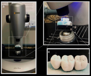
Figure 1. (a) Prosthesis on Sirona InEos Blue scanner base; (b) scanning; (c) silicone-based prosthesis
with the application of Cerec Optispray (Cerec Optispray, Sirona, Bensheim, Germ
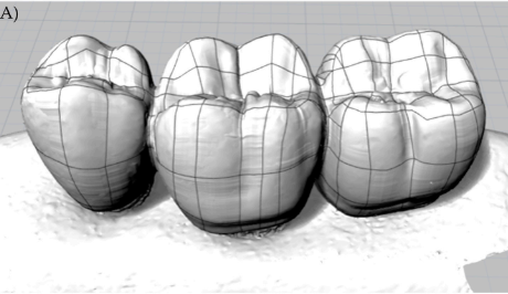
Figure 2. (A) Lines and meshes over the.STL file
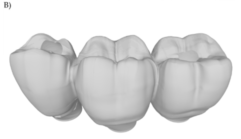
Figura 2 (B) 3D model of the 3-unit fixed partial denture.
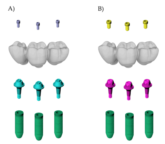
Figure 3. Final geometries according to the groups: (A) CMN; (B) MC
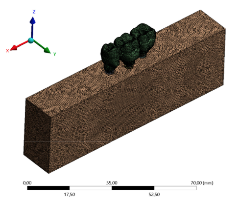
Figure 4. Finite element meshes.
2.2. Strain Gauge Analysis For the strain gauge analysis, 20 polyurethane blocks (95 × 45 × 30 mm) (Polyurethane F16 Axson, Cercy, France) were manufactured to simulate an isotropic substrate for each group (N = 20, n = 10). To prevent pores, the polyurethane resin polymerization was carried out in a vacuum pressurizer (Protecni, Araraquara, São Paulo, Brazil). After the polymerization, the blocks were removed from the matrix and their surfaces were polished with progressive sandpaper (#220 to #600 grit) underwater
A metallic die [17] was used to standardize the three implant placements (4.0 × 13 mm, Intraoss, Sistemas de Implantes, Itaquaquecetuba, SP, Brazil), perpendicular to the surface, at the bone level, and in the “offset” configuration. The respective abutments were installed with the aid of a manual torque wrench and the manufacturer’s guidance, 32 N.cm for the CMN and 20 N.cm for the miniconical abutments (Intraoss, Sistemas de Implantes, Itaquaquecetuba, SP, Brazil). Rotational plastic copings developed for the study were screwed onto the CMN abutments and conventional rotational plastic copings were screwed onto the miniconical abutments (Intraoss, Sistemas de Implantes, Itaquaquecetuba, SP, Brazil).
After the waxed first prosthesis, a condensation silicone template (Speedex, Coltene, Altstätten, Switzerland) was fabricated to ensure that the anatomy of the 3-unit fixed partial denture can be replicated for the other specimens. The occlusal part of the template was removed, and the occlusal part of the prosthesis was copied again with type IV gypsum (Durone, Dentsply Ind. e Com. Ltd. a Petrópolis, Brazil). A total of ten waxed 3-unit fixed partial dentures were completely cast in Ni-Cr alloy (Wironia Light Bego, Bremen, Germany) by lost wax technique for each group. After casting, the specimens were benchcooled and devested by airborne particle abrasion with 50 µm aluminum oxide. Finally, finishing and polishing were performed. All prostheses were screwed on the abutments according to the manufacturer’s recommendation by using a torque wrench (Intraoss, Sistemas de Implantes, Itaquaquecetuba, SP, Brazil).
The surface of the 20 blocks was cleaned with isopropyl alcohol and four unidirectional linear SGs model PA-06-060BA-120-L (Excel Sensores Ind. Com. Exp. Ltd. a, Taboão da Serra, São Paulo, Brazil, resistance 120 Ω; gauge length: 1.5 × 1.3 mm) was bonded to the surface of each block with cyanoacrylate adhesive (Super Bonder Loctite, São Paulo, Brazil). SG1 was placed mesially adjacent to implant #13, SG2 and SG3 were placed mesially and distally adjacent to implant #14, and SG4 was placed distally adjacent to implant #15 [14] (Figure 5).
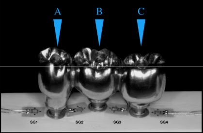
Figure 5. Strain gauges are arranged between the implants and the application load points. Letters
showing the different loading points.